
Why don't machines from the US work over in Europe? Some people did make the mistake of importing now. This type of blunder was not too uncommon, unfortunately. To say it in an untechnical way, there are two reasons for the trouble:
Firstly, we have different colour systems for video (TV) pictures. The one in Europe is called PAL (Phase Alternating Line); in USA and Japan they have NTSC (Never Twice Same Colour... as it was known!). Secondly, we have a different mains frequency to which the TV picture frequency is related. At least the number of lines making up the screen (625 in Europe, 525 in US and 545 in Japan) is not significant in this case.
If you are satisfied with a black and white picture it is possible to retrim al old TV without having to open your computer. We will not handle that subject here, though; I'll deal with tweaking the 64.
To convert from NTSC to PAL a few accessories are needed. There may turn out to be expensive, I'm afraid; but it may be better than to leave your computer unused! Some of the components could be bought in the local radio service shop but most of them have to be bought at a Commodore Service Centre. This is what you need:
New mains unit - do not try to connect the American mains unit to your wall outlet. Alternatively you can buy a stepdown transformer with an input for 220 volts (continental Europe) or 240 volts (UK) and an output of 117 volts to suit the original mains unit.
New VIC chip - the NTSC version is called the 6567 and the PAL version is called the 6569. Different circuitry you see.
New crystal - running at frequency 17.734472 MHz, the NTSC compatible one is different once more.
Ceramic capacitor - rating 15PF.
You have to be very well trained in soldering in order to do this, and if you are in any doubt at all please turn to a friend who can do it for you. The machine has a delicate but well made PC board, double sided, and therefore it is more difficult to work with than something like the board for a hi-fi amplifier.
I must also point out that if you open it the guarantee will be void, which might not do anything in this case because it is only valid in the country where you bought it (Commodore: how about a worldwide guanrantee system?).
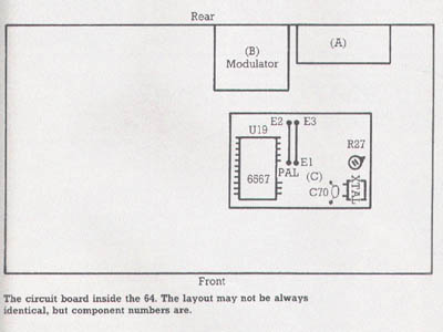
Switch off the computer and take out the mains plug. Open the cover by unscrewing the three screws on the bottom cover, the side normally towards you. Fold the keyboard upwards - be sure not to harm the LED indicator; disconnect it if you like, as well as the cable harness to the keyboard. Loosen the foiled cardboard stuck to the shield of the cartridge expansion port (A). Fold the cardboard over the edge towards you.
Now you can see two tin boxes (B) and (C). Locate the IC called U19 in the (C) area - (C) will usually have a cover which you will have to remove using a small screwdriver.
U19 (or the VIC chip) is a 40 legged integrated circuit and should be marked 6567. Remove this IC, preferably using a special tool (two small screwdrivers may do the trick if they are stuck under the IC at the short sides). Please remember the direction of the IC, usually marked with a small slot on one of the short edges. Now push in your new 6569, in the same direction! The legs may have to be bent somewhat inwards to fit the IC holder properly. Check that all the legs are exactly above their holes; then push evenly over the whole IC trying to get all 40 pins down in their holes at the same time (otherwise the legs may be damaged).
Locate C70 in the same area (C). Desolder the present one and solder the new one there instead. Just beside it you find the crystal; change that too.
Now there is only one more thing to solder and that is the jumper wire, also in the (C) area. In case of an NTSC 64 the jumper goes between letters E1 and E3, printed on the board. Desolder the wire and move it to the adjacent positions, between markings PAL and E2.
Now we shall remove the cover of the modulator (B). It seems that the cover is soldered on at one point on most machines I have seen, so this must be loosened in a special way - dissoldering with one hand, peeling off the cover with the other.
After all this is done it is time to check everything. Make sure that there are no leftover wires and other things than can cause short circuits on the PC board (it is not necessary to reconnect the keyboard yet). Now connect the power supply in both ends and switch on the computer. You should see something that may become a colour picture. Locate a trim potentiometer R27 in the (C) area, near the crystal; turn it gently. Now it should be possible to get a stable colour picture.
If you are dissatisfied with the picture you have to go to the modulator (B). Inside there you can see some trim points; they look different but all have a slot for a screwdriver. These should be turned by a very small screwdriver made of nonmagnetisable material, for instance plastic or copper. Go through the trim points one by one, turning them carefully to either side of their original position, and watch the screen. You should find that one of those controls optimises the picture. Some 64s have a control called R25 which shall also be tried and turned to optimised position.
Then maybe the previous control has to be readjusted again because those controls interact; but finally you will get a good picture. Just do it methodically, and do not rush. Always keep track on how many turns you do in either direction on each control so you know where you started.
Do you have any sound? Connect your keyboard, switch off your computer first. Load a program with sound or make some POKE statements to produce a triangular wave. If there is no sound, or it is distorted, it's time to try and trim those points in the modulator which did not appear to have any effect when you optimised your picture. When doing that you should be able to optimise the sound to become free from distortion.
If by doing this the picture deteriorates again, you should go through the above picture optimising once more, and then the sound again, until everything is okay. Now put the whole thing together again in reverse order. And good luck!
| BACK | (c) 1984, Commodore User |